
When you unpack the boxes please go over all the parts carefully to make
8 ea. 3/4” x 30” long shafts
2 ea. 1/2 ACME 29.5” rods
2 ea. 1/2 ACME 27” rods
2 ea. Large carriages
2 ea. Small carriages
2 ea. Y tower end plates
2 ea. Angled end plates with large holes
2 ea. Angled end plates with small holes
4 ea. 1/2” Teflon bushings
16 ea. 3/4” Teflon bushings
8 ea. Bushing mounting plates (dark red)
4 ea. ACME nuts (white plastic)
2 ea. Motors with long wires
2 ea. Motors with short wires
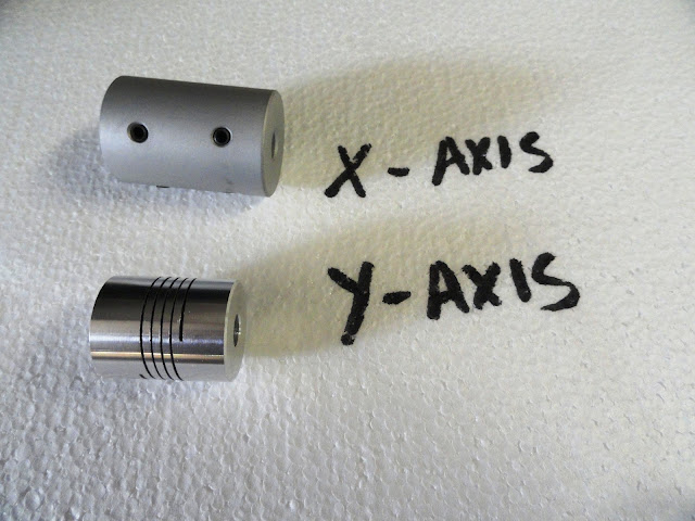
2 ea. High torque motor couplers
2 ea. Standard motor couplers
56 ea. 8-32 Allen cap head screws
32 ea. 8-32 lock nuts
The 1st step is to assemble the X axis carriages (the horizontal axis).
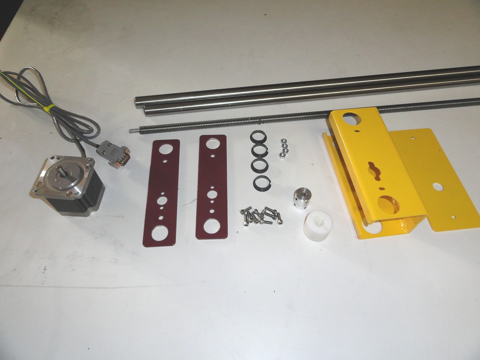
For each carriage you will need the following:
1 carriage (large yellow)
2 bushing support plates (dark red plates)
4 3/4” Teflon bushings
1 ACME nut (white)
6 8-32 Allen screws and 4 8-32 nuts
2 bushing support plates (dark red plates)
4 3/4” Teflon bushings
1 ACME nut (white)
6 8-32 Allen screws and 4 8-32 nuts

Mount the white plastic ACME nut onto the bushing support plates
Using 2 two 8-32 screws, tighten firmly. Insert 3/4” Teflon bushings
with the large ends facing the ACME nut. Sub-assembly should look
like this. Make another, in a similar fashion.
Mount the bushing support plate onto the carriage as shown above, loosely.

Mount the 2nd bushing support plate on the other side of the carriage,
without the white plastic ACME nut using 8-32 screws & nuts, again… loosely.

Another look at the carriage – please double check the 4 bushings,
making sure that the wider side of each Teflon bushings are facing
towards the inside of each carriage (important).
towards the inside of each carriage (important).

In this step we will assemble the complete horizontal axis
rails, to mount the X axis carriages onto. For each unit you will need:
1 The assembled carriage you made in the previous step
1 ea. Motor with short wires
2 ea. Long shafts
1 ea. 29.5” ACME screw
1 ea. Motor with short wires
2 ea. Long shafts
1 ea. 29.5” ACME screw
1 ea. High torque motor coupler
1 ea. 1/2” Teflon bushing
8 ea. 8-32 Screws
4 ea. 8-32 Nuts
1 ea. 1/2” Teflon bushing
8 ea. 8-32 Screws
4 ea. 8-32 Nuts

Insert the two long shafts carefully, making sure that the Teflon bushings
stay in place. Thread the ACME screw about 1/2 way down the ACME screw.

Mount the angled end plate (the one with the larger hole). Make sure thatthe ACME screw with its machined end is facing the hole – this is where thestepper motor will be mounted and connected to the ACME screw via thehigh torque stepper motor coupler. Secure the long shafts using 8-32 screws.

On the other side, mount the angled end plate (the one with the small hole).
Insert the 1/2” Teflon bushing into the small hole, large side facing out.
Screw in the 8-32 mounting screws into the two shafts, as shown above
Insert the 1/2” Teflon bushing into the small hole, large side facing out.
Screw in the 8-32 mounting screws into the two shafts, as shown above

Secure the motor shaft to the ACME screw with the X axis coupler, Making
sure that the coupler does not drag on the motor housing. Tighten coupler

The below image shows both of the entire X carriages, assembled correctly.
 The next step is to assemble the Y (vertical) towers.
For each of the 2 identical towers you will need the following parts-
2 ea. long shafts
1 ea. short ACME screw1 ea. Motor with long wires1 ea. Standard motor coupler2 ea. Bushing support plates1 ea. Y tower end plate1 ea. ACME nut1 ea. Small Carriage4 ea. .750” Teflon bushings10 ea. 8-32 Screws4 ea. 8-32 Nuts


Follow the basic steps shown used before to assemble the Y carriage.
The X carriage is slightly different as it holds a motor.
The X carriage is slightly different as it holds a motor.

Mount the new Y tower onto the horizontal (X) axis as shown above.
Secure the two shafts with two 8-32 screws as shown above. You may want to flip the tower on its side in order to have access to the two mounting screws. Please route the wire away from the ACME screw.
Secure the two shafts with two 8-32 screws as shown above. You may want to flip the tower on its side in order to have access to the two mounting screws. Please route the wire away from the ACME screw.

Now build another tower, similar to the first one.
When you have assembled two of these complete units, set them apart about 24" or so - you can always change the distance between the two towers at a later stage. Loosely snug all bushing mounting plates. These need to have a little play, and should allowed to “float” slightly… by design.
Important… do not mount the completed units to a metal (or electrically conductive) surface.
Hot Wire Hookup
The next step is to connect the eye hooks - the eye hooks are
use to hold the spring on one side and the hot wire
on the other side
Click here for the electronics manual
The next step is to connect the eye hooks - the eye hooks are
use to hold the spring on one side and the hot wire
on the other side
Click here for the electronics manual